7.3 ENGINE THRUST LEVEL CONTROL
The significance of the thrust level of a liquid rocket engine (sea level or vacuum) has been explained in section 2.1. It is usually specified with a tolerance; for instance, " ." It is possible, with modern "fixed thrust level" engines, to guarantee this band with simple orifice calibrations in the various propellant subsystems of the engine, without resort to regu- lators, and with a minimum of calibration firings. However, "thrust" regulators or "controllers" are employed in vehicle systems which require a higher degree of precision and repeatability, such as in single-stage vehicles starting at sea level, or in final stages of a multistage system. Thrust regulators are actually chamber pressure regulators. At altitude (vacuum), their effect is identical to thrust regulation, since at altitude thrust for a given engine and mixture ratio is solely a function of chamber pressure. The same is essentially true for systems starting at sea level, because the relationship of thrust to chamber pressure as a function of altitude is predictable with high accuracy.
Occasionally, vehicle missions will require in-flight thrust control over a wider range. Usually, in such cases, the need is for a planned reduction of thrust, or "throttling," during the last portion of propelled flight. Two basic procedures are possible: (a) Stepwise reduction of chamber pressure, (b) Continuous reduction of
Each of them can be accomplished by control of- (1) Turbine power (in the case of turbopump fed systems), through regulation of gas generator propellant flow rate or hot gas flow rate (preferred method). (2) Main propellant now rate (3) Variation of main tank pressures (in the case of pressure-fed systems). Additionally, in multiple (clustered) engine systems, stepwise thrust reduction can be effected by shutoff of one or more engines of the subsystems.
The example chosen in section 7.1 to illustrate a closed-loop control system is typical for a system effecting thrust control through turbine power variation. Figure 7-3 shows the thrust control system proposed for our A-4 stage engine, which relies on main propellant flow variation. Here, the closed-loop control system operates on the principle of variable fluid resistances in the main oxidizer and fuel feed lines to achieve propellant flow-rate modulation. Engine reaction is determined by sensing chamber pressure, the parameter most indicative of thrust level, and by comparing the feedback with the command reference pressure input . Any resultant error e,
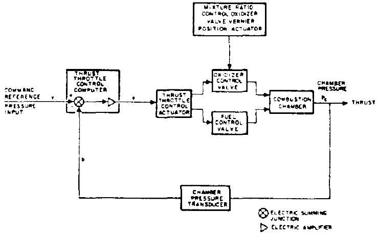 Figure 7-3.-Main-stage thrust throttle control loop for the A-4 stage engine.
following amplification and compensation as required, is used to drive the thrust throttle control actuator of the main propellant control valves in a direction which reduces the error. Ideally, the system operates over the entire thrust throttle range with minimal disturbances to other critical engine parameters; in particular, the propellant mixture ratio. In practice, these disturbances are not entirely avoidable, but can be minimized by maintaining a given resistance ratio between the two main propellant control valves throughout the control range. A most reliable method toward this objective would be mechanical coupling of the two propellant valves (fig. 7-4).
Orifices, propellant valves, and servovalves required for thrust control will be described in subsequent chapters.
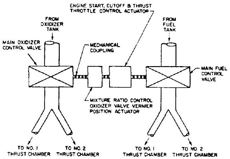 Figure 7-4.-Schematic of the propellant control system for A-4 stage engine start, cutoff, throttle and mixture ratio control.